| About C.GEN | Contact | Press | FAQ |
| North Killingholme Power Project | News | Location | Technology | Planning | Environment | Documents |
| IGCC | Back |


Move the mouse
|
|
12. CO2 compression and Transport (with CCS) |
||
Large volumes of oil, water and gas have long been transported over large distances through pipelines, both over land and sea. Some pipelines lie 2,200 m deep on the seabed. CO2 pipeline transport over large distances is a tested and proven technology. In the Western part of the USA, there is a CO2 pipeline network with a length of more than 2 500 km, through which more than 50 million tons of CO2 per year are transported for use in the petroleum industry (Enhanced Oil Recovery, see step 17). The gas has a pressure of 120-180 bar. Intermediate pump stations keep the CO2 at the required pressure. Large distances can be covered in this way. The composition of the CO2 gas must satisfy certain specifications in order to avoid corrosion, but there are no indications that the operation of a CO2 pipeline system is any more technically difficult than pipeline transport of steam or that it entails more risks than the operation of gas or oil pipelines. |
6. Shift Reactor and Syngas Cooling |
||
The shift reactor is a tank filled with a catalyst through which the syngas passes. The carbon monoxide present in the syngas and the water vapour are converted into carbon dioxide and hydrogen, according to the following “shift reaction”: CO + H2O < = > CO2 + H2 + heat Due to the selection of a gasifier of the direct quench type, sufficient water vapour to complete this shift reaction is already present in the syngas, and no expensive addition of steam from the heat recovery steam generator is necessary. An exceptionally large and expensive shift reactor would be necessary in order to convert 100% of the CO. A conversion rate of 95% of the CO is an economically acceptable compromise which leads to a line-up with two reactors in series, a high-temperature and a low-temperature reactor. This also means that the gas from the outlet of the shift reactor will still contain a small percentage of CO that will go to the gas turbine. This shift reaction is exothermic (releases heat). The heat is recovered in a series of heat exchangers converting boiler feed water into steam at different pressure. This steam will be sent to the steam turbine, where it is transformed into electrical energy. The gasification plant and combined cycle plant are truly “integrated” (The I in the acronym IGCC), increasing the overall efficiency. At the same time the syngas is cooled down to a temperature acceptable for the Acid Gas Removal unit. The shift reaction can be bypassed, e.g. when biomass is used as fuel. |
5. Syngas Cleanup |
||
The gas leaving the gasifier contains fine dust particles (incombustible constituents in the fuel) and small quantities of all kinds of volatile substances, such as ammonia, chlorides, fluorides that may damage the equipment downstream, and, after combustion in the gas turbine, cause harm to the environment. They have to be removed. Thanks to the high pressure, the volatile constituents such as ammonia and hydrochloric acid are readily soluble in water. Together with any residual dust, they are extracted from the syngas in a vessel, the so-called “scrubber”. Water is sprayed at the top of this vessel, filled with packing material to enhance the gas-water contact. The syngas enters the vessel at the bottom, and flows to the top in counter-current with the water. The intense contact so created between water and syngas removes all particles and soluble elements from the syngas. The contaminated water is chemically and physically purified (see 5. Waste Water Treatment Plant”) and reused in the scrubber. |
|
4. Waste Water Treatment |
||
The water, leaving the scrubber, is partly re-circulated, partly treated in the Waste Water Treatment Plant. Gases like ammonia are removed from the water by heating it up and bringing it under increasing vacuum. The recovered gases are sent to an incinerator and transformed into nitrogen, carbon dioxide and water. The degassed water is sent to a clarifier, after adding flocculants. The underflow of this clarifier, containing all solids, is sent to a vacuum belt filter, separating the solids from the water. These solids form a filter cake, which can, for the major part, be recycled to the coal yard to be transformed, during the second passage through the gasifier, into unleachable slag. The waste water is further chemically and biologically treated to bring its composition within the stringent specifications for discharge into brackish or saline surface water. |
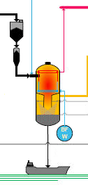
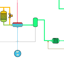
3. Gasification |
||
|
Coal gasification processes have been around since the early 20th Century. Historically, synthetic gas (a mixture of essentially H2 and CO) was produced for use as town gas, for the production of all kinds of chemicals and for the production of hydrogen which is a base material in the production of ammonia (fertilizer production).
There are numerous gasification technologies, but C.GEN has opted, after an exhaustive technical and economic comparison, for a technology based on the use of pure oxygen as oxidant, the injection of dry pulverized solid fuel (e.g. coal, biomass) into the gasifier, a pressurized entrained flow gasifier with a membrane wall (the walls of the pressurization vessel are protected against overheating by a tube wall, cooled by water/steam), and a direct water quench system, meaning that the hot gases at 1 600°C coming out of the gasification section are abruptly cooled down to 200°C by injecting huge quantities of finely pulverized water into this gas stream. This choice assures, for a plant with CO2 capture, a good overall plant efficiency and availability, and allows for a very flexible fuel selection. The heart of a gasification plant is the gasifier. This is a large vessel with an internal pressure of approximately 45 bar, in which pulverized solid fuel is injected by a stream of nitrogen, together with a small stream of pure oxygen. Part of the solid fuel reacts with the oxygen (combustion), raising the temperature to 1 400 - 1 600 °C. Due to the high temperature and pressure in the gasifier, the complex molecules of the fuel are broken down into simple molecules according to the following reactions: C + ½ O2 => CO (combustion) CO + H2O < = > CO2 + H2 (shift reaction) The produced synthetic gas (syngas) consists mainly of carbon monoxide (CO), carbon dioxide (CO2), hydrogen (H2) and water vapour (H2O). The fuel also contains small quantities of sulphur, nitrogen, chlorine, etc. They are mainly converted into H2S (hydrogen sulphide), HCl (hydrochloric acid), NH3 (ammonia), etc. These volatile substances can be easily removed from the syngas (see 4. Syngas Clean-up). The solid fuels also contain incombustible constituents such as sand, clay and minerals. About 80% of these will melt and stick to the walls of the gasifier, then flow down slowly into the water bath beneath where they cool down to form glassy flakes called “slag”. The solidified slag locks into its glassy structure a number of impurities present by nature in the solid fuel. This prevents these from ever being released back into the environment. Besides the slag, also fine inert particles, called fly ash, are produced. This ash is entrained by the gas flow and partially precipitated in the quench section of the gasifier. The remaining part is captured by the downstream scrubber. Both slag and fly ash can be reused in the construction industry (concrete and cement production, road-building). |
| 2. Oxygen Production | ||
Ambient air, consisting of 21% oxygen, 78% nitrogen and 1% other gases, is dried and purified before entering the Air Separation Unit (ASU). The air is then compressed to 5 -8 bar and cooled to around minus 190°C by expanding to a lower pressure level. At this very low temperature, oxygen becomes liquid, while the nitrogen, which has an even lower boiling point, remains mostly in the gaseous phase. The two fluids can then easily be separated from each other by distillation. Afterwards, the liquid oxygen is converted back to gas in a heat-exchanger, recovering energy. Pure oxygen and nitrogen at the outlet of the ASU are brought to the required pressure by compressors. The oxygen is fed to the gasifier, while the nitrogen is used for coal pressurization and transportation, and to dilute the hydrogen before entering the gas turbine. |
10. Heat Recovery Steam Generator (HRSG) |
||
The exhaust gases from the gas turbine have a temperature of 600°C and still contain a large amount of energy. That energy is used in the HRSG for steam production at different pressure levels. The steam is then sent to the steam turbine for additional electricity production. Saturated steam, produced by the membrane walls of the gasifier and by the syngas coolers downstream of the shift reactor is sent to the HRSG to be superheated. This superheated steam flows to the steam turbine, increasing the electricity production. In this way, the integration between gasification plant and combined cycle plant is realized. The outlet gases from the gas turbine consist mainly of water vapour (mainly resulting from the combustion of the hydrogen), nitrogen and a small quantity of carbon dioxide. NOx, SO2 and dust emissions to the air from this type of power plant are of the same order of magnitude as those from a conventional natural gas-fired CCGT. |
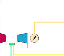
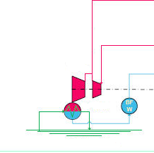
9. Gas Turbine |
||
When the CCGT is fuelled by syngas of the gasifier, the gas, at a pressure of approximately 30 bar, is diluted with nitrogen (produced by the air separation unit) and water vapour. This dilution allows the mixture to be used in a (sometimes slightly modified) modern, efficient and flexible F Class gas turbine, and decreases the NOx-production in the gas turbine. The gas turbine drives a generator producing electricity for the high voltage transmission grid. The exhaust gases from the gas turbine are sent to the heat recovery steam generator, which recovers the heat present in the exhaust gas for steam production. The gas turbine can also run on natural gas. |
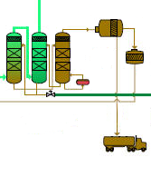
8. Hydrogen Purification |
||
Hydrogen consumers usually have stringent requirements with regard to the purity of their feedstock. A purity requirement of more than 99.99 volumetric % H2 is not exceptional. In order to attain this high value, the hydrogen is passed through molecular sieves that remove all residual gases like CO2, CO, N2 etc. out of the hydrogen rich gas. This is done in a Pressure Swing Adsorption (PSA) unit. This is comprised of vessels, filled with zeolite, through which the syngas flows. This mineral allows most of the hydrogen to pass through and absorbs all the other molecules on its surface. Over time, the zeolite becomes saturated and has to be regenerated. This is done by isolating the first vessel and switching the gas flow to an identical second standby vessel. The pressure in the first vessel is then reduced, releasing the impurities such as CO2, CO and N2, together with a small amount of H2. This residual gas is sent to the gas turbine for combustion. |
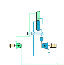
7. Acid Gas Removal (with CCS) |
||
Downstream of the shift reactor the syngas consists mainly of carbon dioxide and hydrogen. However, any sulphur present by nature in the fuel will lead to the presence of a small quantity of H2S gas in the syngas. To remove the H2S together with the unwanted CO2, the syngas flow is brought into close contact with a liquid organic solvent (a glycol) in two consecutive scrubbers. These are vessels filled with balls. The solvent is dispersed from the top of the vessel and flows down, covering the surface of the balls. The syngas is injected from the bottom and flows upwards through the voids between the balls. In this way, the contacting surface syngas/solvent is increased drastically. The high pressure and relatively high concentrations of CO2 and H2S (due to the absence of nitrogen) render these gases readily soluble in this solvent. Due to a difference in solubility, the solvent in the first scrubber is saturated with H2S and in a second scrubber with CO2. The gas leaving the top of the second scrubber contains practically only H2, almost no H2S and only a small quantity of carbon dioxide, carbon monoxide and nitrogen. The saturated solvent first undergoes pressure reduction in a regeneration vessel to release the absorbed CO2 (this can be compared with opening a bottle of sparkling wine where the pressure is reduced by removing the cork: the absorbed CO2 forms bubbles that escape at the top). The solvent is then free of CO2, but still saturated with H2S. Still saturated with H2S, the solvent is run to a third vessel (stripper) where it undergoes some minor heating. The H2S is hereby separated from the solvent in just the same way as dissolved air is released from water when heated. The solvent is then ready to be reused and is run back into the first scrubber where the cycle can start all over again. The H2S at the top of the stripper goes to a Claus unit which converts the H2S gas into elementary sulphur and water. The captured carbon dioxide is compressed for further treatment (see below) and the solid sulphur is used as feedstock in the chemical industry (e.g. for the production of sulphuric acid). The high pressure in the entire gasification plant and the absence of large amounts of atmospheric nitrogen render the whole purification process highly efficient (low energy consumption) and results in very low residual sulphur content in the hydrogen rich gas going to the gas turbine (even with high sulphur content in the feedstock).
|
11. Steam Turbine |
||
The steam from the HRSG, together with the steam produced in the gasification plant is expanded in a steam turbine which drives the same generator as the gas turbine: gas turbine, steam turbine and generator share the same shaft. The expanded steam from the steam turbine is condensed in a condenser which is in turn cooled by cooling water. The condensate is used again and sent back to the HRSG and gasification plant. |
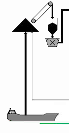
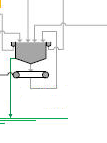
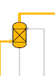
1. Fuel Preparation |
||
UK or imported coal, petroleum coke or wood pellets are offloaded from the train or from barges, handymax or panamax sized ships and stored on the on site coal yard. An entirely covered coal yard with a capacity of approximately 150.000 tons, enough for thirty days of full capacity plant operation, stores the solid fuels on the C.GEN production site. Covered conveyor belts bring the coal from the storage to the coal preparation plant. In the coal preparation plant, the coal is pulverized and dried, and stored in the pulverized coal bin. From there, the coal is pressurized, sent to the gasifier by a stream of nitrogen, and transformed into syngas. Given the very high efficiency of the gas clean-up and desulphurization equipment used, very low sulphur emission levels can be realized, even processing solid fuels with high sulphur content. |
| Air emissions | |||
| N2 | 70%vol | ||
| H20 | 16%vol | ||
| O2 | 12%vol | ||
| CO2 | 1%vol | ||
| NOx | < 50 mg/Nm³ | ||
| SOx | < 1 mg/Nm³ | ||
| (%vol = percent by volume) | |||
| Composition Syngas | ||
| H2 | 13 to 16%vol | |
| CO | 27 to 30%vol | |
| CO2 | 2 to 4%vol | |
| N2 | 3 to 4%vol | |
| H2S | 0,1 to 0,5%vol | |
| H2O | 50 to 54%vol | |
| (%vol = percent by volume) | ||
| Composition Air | |||
| O2 | 21%vol | ||
| N2 | 78%vol | ||
| Ar, CO2 etc | 1%vol | ||
| (%vol = percent by volume) | |||
| Clean Waste Water | ||
| The water leaving the scrubber contains also contains dissolved gases (chlorides, fluorides, ammonia etc.). A highly efficient waste water treatment plant will remove all these substances almost completely from the waste water by precipitating, filtering and degassing. The recovered waste gases will be neutralized by combustion. The waste water will undergo further physical and biological treatment to ensure that discharge consent conditions are fully satisfied. |
||
| Filter Cake | ||
| Part of the inert material, molten in the gasifier will be entrained by the syngas flow and solidify in the form of small particles (fly ash) by cooling down in the water sprayed section of the gasifier. These particles are further washed out from the syngas by water in the syngas clean-up section (the so-called scrubber). The water coming out of the scrubber is treated to remove all undesirable components and filtered before discharge. This process produces a so-called filter cake having approximately the same composition as the slag. This filter cake can be used in the building industry or for road construction, or for the major part be recycled to the coal yard. | ||
| Composition Hydrogen - CO2 |
|||
| H2 | 52 to 54%vol | ||
| CO | 3 to 4%vol | ||
| CO2 | 38 to 42%vol | ||
| N2 | 1 to 6%vol | ||
| H2S | 0.2 to 0.6%vol | ||
| H20 | 0 to 0,2%vol | ||
| (%vol = percent by volume) | |||
| Fuel | ||
| Type composition (in % by weight) of e.g. coal |
||
| Moisture | 6 to 14 % | |
| Ash | 4 to 16 % | |
| C | 56 to 72 % | |
| H | 2 to 6 % | |
| O | 2 to 12 % | |
| N | 0 to 2 % | |
| Slag | ||
| Solid fuels contain combustible constituents like carbon and hydrogen, and incombustible constituents like sand, clay, and some trace elements as all geological resources do. These incombustible constituents will melt when exposed to the high temperatures (1400 – 1600°C) inside the gasifier. The major part of these molten particles will adhere to the membrane wall of the gasifier, flow down along its walls and cool and solidify in the water bath at the bottom of it. This solidified material called “slag” locks in irrevocably all mineral constituents, preventing their release into the environment (in other words, these elements can never leach out). The slag product is stored in closed silos for ultimate use in the construction industry where it is primarily used in concrete production and road construction. | ||
| Sulphur | ||
| The sulphur leaves the residual gas installation in the form of powder or lumps and is stored in a closed silo before transport. In the chemical industry, sulphur has many uses as a raw material for various compounds. Large consumers of sulphur are found in the production of sulphuric acid and in the rubber industry, where it is used for vulcanization. | ||
| Composition Hydrogen Rich Gas |
|||
| H2 |
84 to 86%vol | ||
| CO | 3 to 4%vol | ||
| CO2 | 3 to 4%vol | ||
| N2 | 7 to 8%vol | ||
| H2S | traces | ||
| H20 | traces | ||
| (% vol means percent by volume) | |||
| Composition CO2 | |||
| CO2 | 98 to 99%vol | ||
| CO, H2 etc | 1 to 2%vol | ||
| %vol = percent by volume | |||
| Composition Oxygen | |||
| N2 | 1,5 %vol | ||
| O2 | 95 %vol | ||
| Ar | 3,5 %vol | ||
| %vol = percent by volume | |||
| Composition Nitrogen | |||
| N2 | 97,5 %vol | ||
| O2 | 2,15 %vol | ||
| Ar | 0,26 %vol | ||
| H2O | 0,09 %vol | ||
| %vol = percent by volume | |||