| North Killingholme Power Project | News | Location | Technology | Planning | Environment | Documents |
| Carbon Capture and Storage | Back |
Click |
||
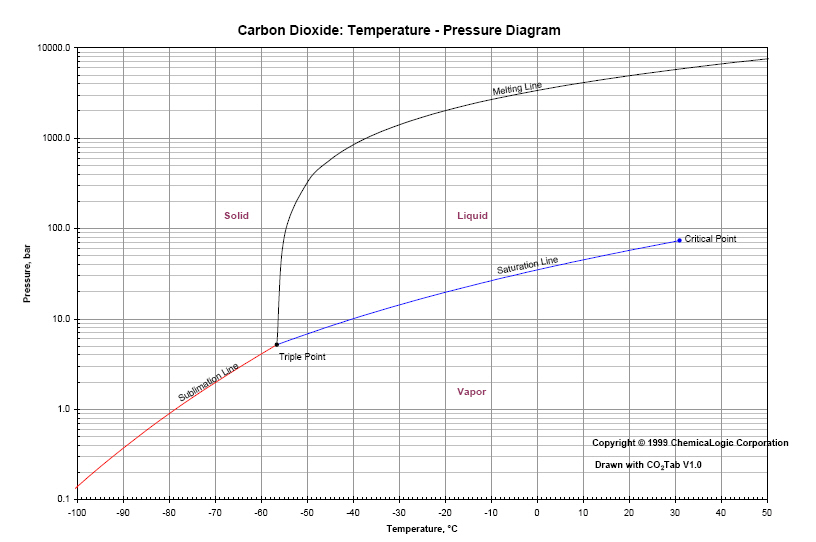
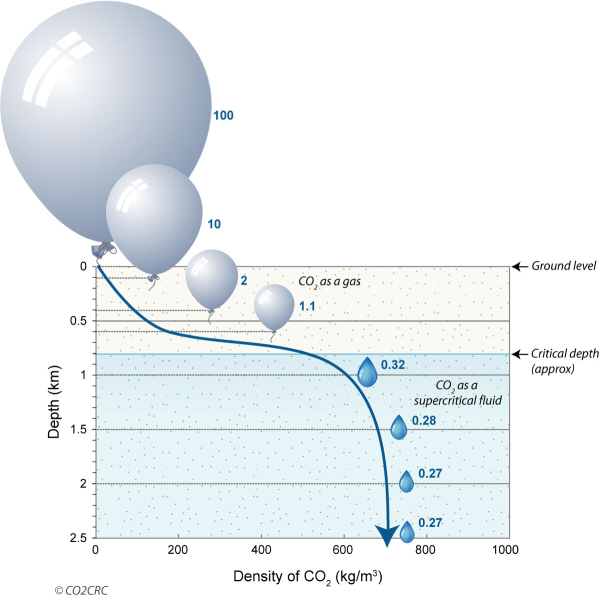
12. CO2 Compression & Transport CO2 at atmospheric pressure has a density of around 2 kg/m³ and is approximately 1.5 times heavier than air. Transport of CO2 under atmospheric pressure takes up very large volumes and would require very large and expensive installations. When compressed, the volume becomes much smaller and transport via pipelines becomes much easier. If the pressure is increased above 74 bar and temperature above 32°C, which is the so-called critical point on the phase diagram, the CO2 becomes “supercritical”. The density is then approximately 800 - 900 kg/m³, which is very convenient for pipeline transport. Another way to increase the density of CO2 is to cool it and compress it to just above the so-called “triple point” (-56.6 °C, 5.2 bar) on the phase diagram. The CO2 is then called “liquid”, and its density is then around 1200 kg/m³. In this case, pipelines and tanks must have sufficient thermal insulation and the materials must be capable of withstanding the low temperatures. This is the recommended method for transport by ship because of the relatively low pressure necessary. |
||

| Composition CO2 | |||
| CO2 | 98 to 99%vol | ||
| CO, H2 etc | 1 to 2%vol | ||
| %vol = percent by volume | |||
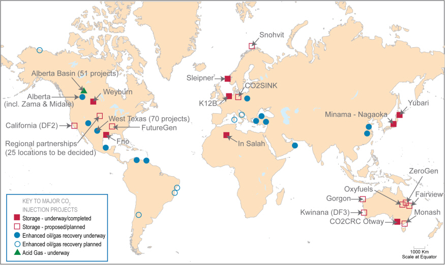
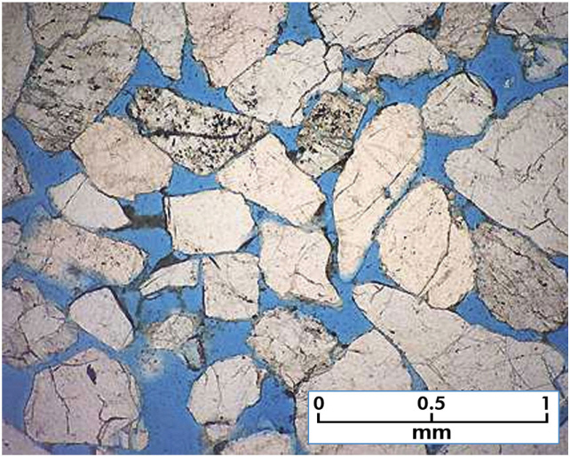
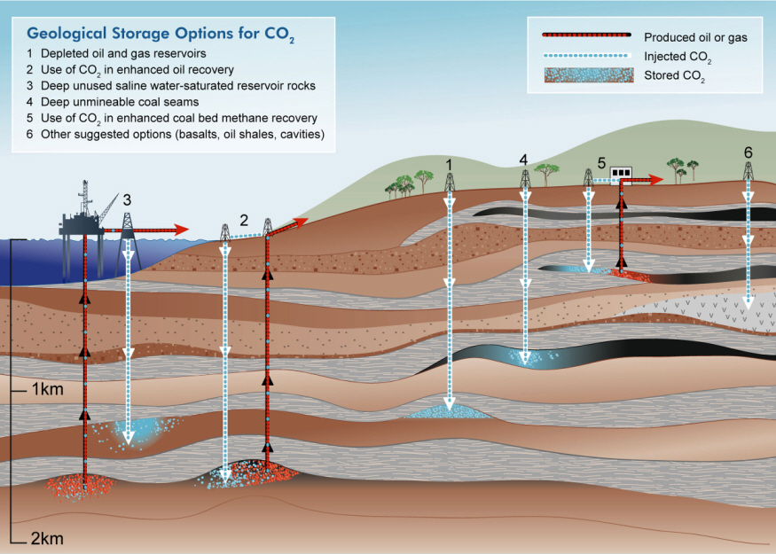
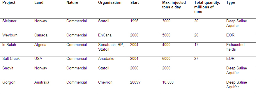
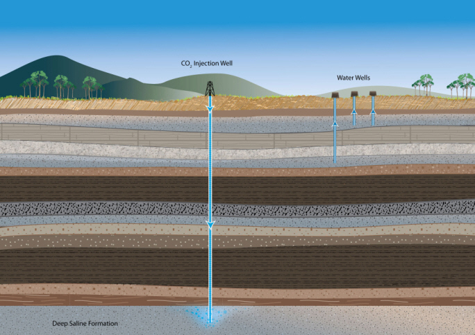
15. CO2 - Storage Underground natural CO2 reservoirs are well known geological formations. In the US, CO2 originating from these natural reservoirs has been used for decades for 'Enhanced Oil Recovery' (see step 17). This is a technique where CO2 is pumped into an oil well in order to force out the remaining oil. Information from CO2 storage projects like “Sleipner”, “In Salah” and “Weyburn” indicate that it is possible to permanently store CO2 in underground reservoirs. Seasonal storage of similar gases like natural gas in underground reservoirs confirms the same. It is estimated that once stored, the CO2-leakage will be less than 1% in 1 000 years. Such a reservoir usually consists of a dome-shaped porous sandstone layer, covered with a layer of impermeable rock (caprock). Oil, gas or saline water is captured in the gaps between the sandstone grains. When the oil or gas is extracted from these gaps the empty voids can be filled with CO2. Depleted oil and gas fields and deep saline formations are suitable for the geological storage of CO2. Deep saline formations are subterranean porous layers, often sandstone, which pores are filled with very salty water, unsuitable for consumption. They are usually at a depth of 800 - 1000 m where the pressure is approximately 80 - 100 bar. From 80 bar onwards, the CO2 density increases significantly and the supercritical CO2 is in a dense phase ( see phase diagram). CO2 remains enclosed in the pores, dissolves in the water or forms chemical compounds with the minerals present and is immobilized for very long periods. Besides many pilot and demo projects, there are currently a number of commercial large-scale CO2 storage projects. |
||
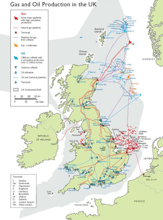
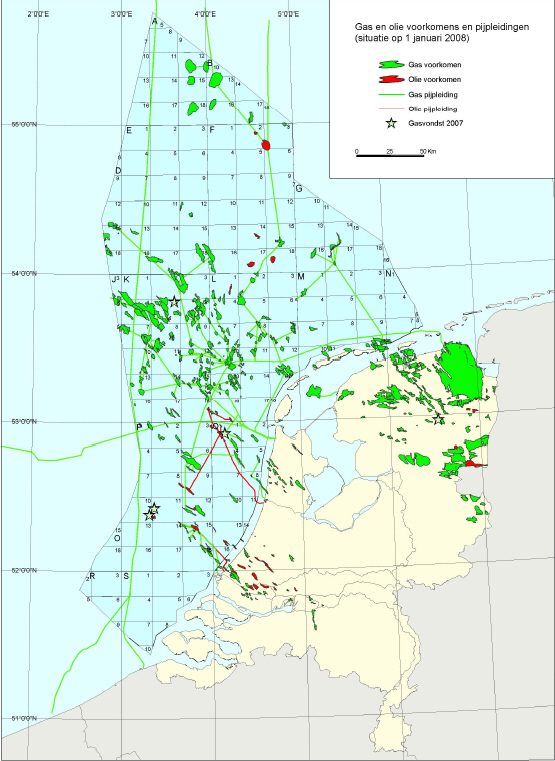
16. Depleted Olie & Gas fields The storage of CO2 in depleted oil and gas fields is a promising technique. The fact that these reservoirs have kept their oil or gas over millions of years means that they have been 'tight' in the past and will most probably not leak to the surface. Furthermore, all the main parameters of these fields, such as geometry, porosity, etc., are well known and the main infrastructure such as production platforms is already in place. In the North Sea, off the UK and Dutch coast are many small to medium-sized oil and gas fields, some of which are nearing the end of their production period. This creates opportunities for the geological storage of CO2. |
||
17. Enhanced Oil Recovery (EOR)– Enhanced Gas Recovery (EGR) CO2 is injected in various places in oil fields to increase their production. Since 1970, in West-Texas, US, 30 million tons per year of natural CO2, extracted from geological CO2 reservoirs, is injected in various oil fields to enhance their yield.The Weyburn project in Canada injects 1 to 2 million tons of CO2 per year into oil fields which have a total capacity of 20 million tons. Enhanced Oil Recovery is carefully monitored and modeling programs are used for the evaluation of this CO2 storage. The extra oil production is 10 000 barrels/day. There have been no signs of leakage so far. |
||
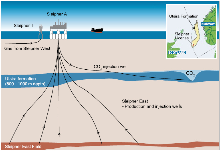
18. Deep Saline Formations Deep salty water-bearing layers are generally assumed to have the largest CO2 storage capacity worldwide. In these deep underground porous layers, often sandstone, the pores are filled with highly saline water, unfit for any use. They are separated from layers with water fit for human consumption by impermeable rock. In the Sleipner gas field, operated by Statoil, the natural gas contains up to 9% CO2. Since 1996 this CO2 has been separated from the natural gas and injected in the 'Utsira Formation', a saline water-bearing aquifer, at a depth of 800 - 1000 m, with a flow rate of 1 million tons per year. This sandstone formation has a very high storage capacity of the order of magnitude of 1 to 10 million tons of CO2. From the start of the actual CO2 storage, the distribution of the CO2 was closely monitored by seismic imaging. Analysis of the results indicates that the overlying impermeable rock layer (caprock) effectively prevents any release of CO2. |
||
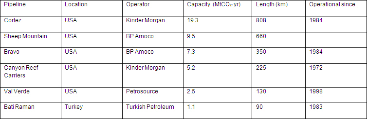
13. Transportation by Pipeline Large volumes of oil, water and gas have long been transported over significant distances through pipelines, both over land and sea. Some pipelines lie 2,200 m deep at the seabed. CO2 pipeline transport over large distances is a tested and proven technology. In the Western part of the USA, there is a CO2 pipeline network with a length of more than 2 500 km, through which more than 50 million tons of CO2 per year are transported for use in the petroleum industry (Enhanced Oil Recovery, see step 17). The gas has a pressure of 120-180 bar. Intermediate pump stations keep the CO2 at the required pressure and large distances can be covered in this way. The composition of the CO2 gas must satisfy certain specifications in order to avoid corrosion, but there are no indications that the operation of a CO2 pipeline system is any more technically difficult than pipeline transport of steam or that it entails more risks than the operation of gas or oil pipelines. |
||
| 14. Transportation by Ship
For decades, liquefied natural gas and liquefied petroleum gases (LPG) such as butane and propane have been transported on a large scale by sea in tanker ships. Similar transport also exists for CO2, of course on a smaller scale, due to the more the limited demand. The properties of cryogenic CO2 are not that different from those of the above mentioned gases and the same technologies may be applied. Practically, CO2 is compressed to 6 bar and cooled to -55 °C in a special cooling plant, which operates basically on the same principle as a refrigerator. Tankers can provide transport between the production plant and the storage location. Some space must also be arranged on the production site for temporary storage of the cryogenic CO2. The technology for the loading and offloading of such products is well known and developed. The advantages of transport by ship compared to pipeline transport are flexibility in the destination of the CO2 and rapid deployment of the transportation route. |
||
| Copyright © C.GEN 2012 - All rights reserved - Terms of Use - Privacy Policy |